
Why modern compact medium-voltage metal-enclosed capacitor banks and harmonic filter banks should utilize direct fuse status indication rather than relying solely on indirect unbalance protection schemes such as neutral voltage and split-wye neutral current schemes.
Brief No.: VEB-001
Category: Protection / Blown Fuse Detection / Capacitor Banks / Harmonic Filter Banks
1. Introduction
Direct blown fuse detection is an important protection strategy in modern medium-voltage metal-enclosed capacitor banks and harmonic filter banks, particularly in compact, lower-MVAR designs where the loss of a single fused capacitor unit can overvoltage the remaining capacitors. In these applications, protection must do more than identify fuse operation. It must also limit remaining-unit overvoltage, avoid prolonged operation in a detuned filter condition, and reduce the risk of fuse failure that can result in flashover.
This brief explains why traditional indirect unbalance schemes may be insufficient in certain compact bank configurations and why direct fuse sensing with thermal actuation is often the more appropriate protection approach.
2. Why This Matters
The blown fuse detection method used in a metal-enclosed capacitor bank or harmonic filter bank directly affects protection performance, reliability, commissioning, maintenance, and specification quality.
If a failed capacitor unit is not detected promptly, the remaining units in the affected group may be subjected to elevated voltage, leading to cascading capacitor failure. In harmonic filters, a blown fuse can shift the filter away from its intended tuning point, resulting in degraded performance, reactor overload, or resonance concerns.
These risks are often more severe in compact metal-enclosed banks because fewer capacitors are used per stage, leaving less margin than in larger open-rack arrangements with more units in parallel.
This issue also matters at the specification stage. Many project documents call for “blown fuse detection” without clearly defining the required protection objective. That can lead to a scheme that indicates bank unbalance but does not address fuse overheating, ambiguous failure indications, or prompt removal of the affected stage. In practice, that can result in a design that meets the written specification yet still does not provide the level of protection the equipment needs in service.
3. Technical Discussion
3.1 Compact metal-enclosed designs change the protection problem
IEEE Std C37.99-2012 – Guide for the Protection of Shunt Power Capacitors Banks states that one basic design objective in an externally fused capacitor bank is to ensure that removal of a single capacitor unit does not impose unacceptable voltage stress on the remaining units in the same series group. In practice, this open-air design philosophy leads to the use of at least four capacitors in parallel per stage per phase. That approach requires smaller individual capacitor units and a higher component count, including more fuses, capacitors, insulators, and buswork, which increases footprint and cost.
Metal-enclosed capacitor banks are designed with a different priority. Because a compact footprint is desired, these banks typically maximize capacitor unit size and use fewer capacitor units in parallel. As the number of capacitors per stage per phase drops below four, the loss of one capacitor causes a greater voltage rise on the remaining units and, in harmonic filter applications, a greater shift in tuning point.
In addition, the time-current characteristics and operating principles of current-limiting fuses increase the risk of fuse failure under low-current fault conditions. The resulting fault current due to a failure or partially failed capacitor may be insufficient for prompt interruption and can instead subject the fuse to prolonged thermal stress.
For these reasons, the protection question in compact metal-enclosed banks is not only whether a capacitor has failed or a fuse has operated. It is whether the affected stage is removed from service before remaining-unit overvoltage, filter detuning, or fuse failure develops.
3.2 Fuse overheating is a separate protection concern
Medium-voltage current-limiting fuses are highly effective for interrupting substantial fault current and are excellent protective devices when operating within their intended short-circuit range. During these high-current events, the fuse rapidly limits the current and safely quenches the arc.
However, the situation changes significantly under low-current fault conditions. In compact metal-enclosed capacitor bank arrangements, particularly ungrounded banks using four or fewer capacitors per stage, the available fault current from a failed capacitor is only three times the normal stage current for a fully failed capacitor and even less for a partially failed capacitor. This current may be too low (see figure 1) to drive the fuse promptly into its intended current-limiting clearing region, placing it in an unsafe operating range.
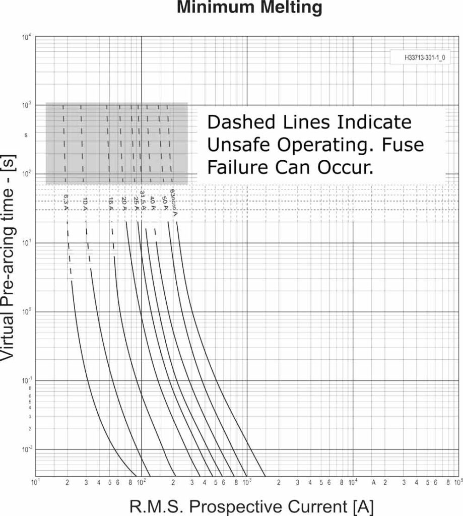
Figure 1 – Operation in the low current range of a current limiting fuse for extended periods of time can result in fuse failure.
Instead of interrupting promptly, the fuse can remain energized for an extended period and continue heating. This prolonged overload can drive the internal silver fuse elements toward their melting temperature, with internal temperatures approaching about 1000°C. As the fuse overheats, the fuse tube and housing can be severely damaged, the arc-quenching sand can be lost, and improper clearing can result. The end result may be catastrophic multi-phase flashover and major enclosure damage.
This is a different protection problem from the one addressed by conventional bank unbalance protection. A scheme that indicates electrical unbalance in the bank does not necessarily detect a fuse that is entering thermal failure.
3.3 Traditional unbalance protection relies on indirect detection
Historically, blown fuse detection has often been accomplished through indirect unbalance protection. See Figure 2. These schemes typically use a voltage transformer, current transformer, or equivalent sensor together with a protective relay. The relay is set to respond to the magnitude and duration of the resulting unbalance signal.
In ungrounded single-wye banks, this is commonly implemented as a neutral voltage unbalance detection scheme, typically using a PT or voltage divider arrangement together with an overvoltage relay. In double-wye configurations, neutral current unbalance detection is widely used to measure the circulating unbalance current between the neutrals of two parallel wye-connected banks, typically using a CT and an overcurrent relay.
Both methods have long been used successfully, particularly in open-air capacitor banks with many capacitor units, where they can often be arranged to alarm on an initial blown fuse condition and trip on a later additional blown fuse condition. This was a more significant advantage in earlier capacitor designs, when paper was commonly used as the primary dielectric and capacitor failure rates were higher. With modern polypropylene dielectric capacitor units, which have much higher reliability, this advantage is less important than it once was.
Neutral voltage unbalance detection does have drawbacks. It can be susceptible to false tripping caused by system voltage unbalance, unequal phase-to-ground capacitance, or neutral voltage shift resulting from remote line-to-ground faults. Protective coordination must be evaluated carefully for the latter condition. In addition, the presence of the neutral PT can increase the likelihood of switch restrike by affecting TRV during switching.
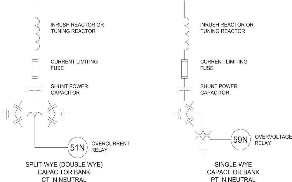
Figure 2 – Traditional Unbalance Detection Schemes
Neutral current unbalance detection has the practical advantage of not generally being affected by normal system voltage unbalance or remote ground faults. It also avoids the TRV-related switching concerns associated with neutral PTs. For these reasons, VarStec recommends neutral current unbalance as the preferred indirect method where an indirect blown fuse detection scheme is desired, either as primary protection or as backup to direct fuse sensing. This method is not without limitations, however. Under certain canceling failure conditions, such as two fuses operating on the same phase in opposite wye groups, their effects can cancel and the blown fuse condition may not be seen by the neutral current unbalance scheme.
Both methods are established and can be appropriate in larger metal-enclosed capacitor bank or harmonic filter applications. However, both remain indirect methods. They respond to secondary electrical effects rather than to the fuse itself, and they do not protect against fuse thermal failure.
3.4 Direct fuse sensing provides direct indication and fuse-level thermal protection
Direct fuse sensing addresses the protection problem by monitoring the fuse itself rather than inferring a fuse event from electrical unbalance elsewhere in the bank.
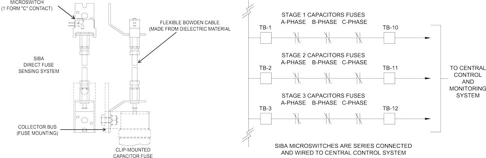
Figure 3 – Siba Direct Fuse Sensing
In the approach VarStec applies (see figure 3), striker-equipped medium-voltage current-limiting fuses manufactured by SIBA are connected to a microswitch assembly through a flexible dielectric Bowden cable. When the fuse operates, the spring-loaded striker pin deploys and actuates the cable, which changes the state of the microswitch. That microswitch provides a direct input to the PLC or control system, which can immediately trip and lock out the affected capacitor or filter stage.
This provides a clear and unambiguous indication of fuse operation at the individual fuse level and gives the control system a direct basis for prompt stage removal.
The SIBA-based arrangement also adds an important protection feature at the fuse level. In addition to indicating conventional short-circuit fuse operation, it includes an integrated temperature-limiter function that responds to fuse overheating under low-current overload conditions. In this situation, the current may be too low to drive prompt fuse interruption, but still high enough to subject the fuse to prolonged thermal stress. Before destructive fuse failure develops, the thermal limiter actuates the striker pin and allows the control system to trip the affected stage offline.
This added thermal actuation directly addresses the fuse-overheating problem described above. It provides protection that conventional neutral unbalance schemes do not provide, because those methods do not monitor fuse temperature. For this reason, the SIBA direct sensing approach remains valuable even where an indirect unbalance scheme is retained for alarm, backup, or other design reasons.
4. Engineering Considerations
When evaluating blown fuse detection for a metal-enclosed capacitor bank or harmonic filter bank, engineers should consider the following:
- the number of capacitors in parallel per phase or per stage, and the resulting voltage rise on the remaining units after one fuse operation
- whether the application is a capacitor bank or a harmonic filter bank, since filter detuning may become a primary concern
- whether the selected scheme detects only bank unbalance or directly detects fuse operation and fuse thermal actuation
- whether the bank configuration allows ambiguous or canceling indications under certain failure combinations
- whether switching-duty implications, including TRV and restrike considerations, are affected by the sensing method or by the use of neutral PTs
- whether the specification clearly defines the required protection objective, rather than simply calling for “blown fuse detection”
For metal-enclosed capacitor banks and harmonic filter banks, conventional neutral unbalance protection alone does not protect against fuse failure caused by thermal overload. VarStec recommends the SIBA direct blown fuse detection system, either as the primary blown fuse detection method or as a backup to split-wye neutral current unbalance protection where that scheme is also used. Fuse failure due to thermal overload is a significant threat to equipment reliability and should always be addressed in metal-enclosed projects. Direct thermal actuation should be required. Without it, the equipment remains exposed to a damaging failure mode that conventional unbalance protection does not address.
5. Standards and Additional Resources
- IEEE Std C37.99, Guide for the Protection of Shunt Capacitor Banks
Useful for understanding capacitor bank protection methods, unbalance protection theory, and the practical limitations of certain bank configurations. - IEEE Std 18, Standard for Shunt Power Capacitors
Relevant for capacitor capability limits and voltage withstand expectations after a capacitor unit is lost. - IEEE Std 1036, Guide for the Application of Shunt Power Capacitors
Helpful for capacitor application limits, system behavior after unit loss, and broader design considerations affecting protection philosophy. - IEEE Std 1531, Guide to the Application and Specification of Harmonic Filters
Particularly relevant in filter applications where fuse loss can affect tuning, overload performance, and overall filter behavior. - All IEEE documents can be downloaded directly from the IEEE Standards Store https://standards.ieee.org/access-standards/
- SIBA High Voltage Fuse Catalog https://www.siballc.net/
Useful for product-specific information on fuse construction, striker-equipped designs, temperature-limiter functionality, and available microswitch monitoring assemblies. Product details should be confirmed against the exact fuse family being applied. - Related VarStec Resources
VarStec application materials, technical tools, and future engineering briefs can be used to support project-specific review of blown fuse detection strategy, fuse selection, and protection philosophy.
6. VarStec Perspective
VarStec approaches blown fuse detection as a protection design issue, not simply as an alarm or compliance feature. In metal-enclosed capacitor banks and harmonic filter banks, the protection objective must include not only indication of fuse operation, but also prevention of fuse thermal failure and prompt removal of the affected stage before enclosure damage can develop.
For that reason, VarStec favors direct fuse sensing with thermal actuation in metal-enclosed designs. Where an indirect scheme is also desired or required, VarStec prefers split-wye neutral current unbalance rather than neutral voltage detection using PTs, due to the latter’s exposure to false-trip conditions and TRV-related switching concerns.
7. Key Takeaway
For metal-enclosed capacitor banks and harmonic filter banks, SIBA direct fuse sensing with thermal actuation should be specified as a required protection feature. Conventional neutral unbalance protection does not protect against fuse thermal failure.
8. Contact / Further Information
For engineering guidance, application review, or equipment support related to metal-enclosed capacitor banks, harmonic filter banks, blown fuse detection, switching duty, or motor-start solutions, contact VarStec. VarStec combines practical engineering expertise with equipment solutions for medium-voltage reactive compensation and power quality applications.
About the Author
Paul B. Steciuk is Co-Founder and President of VarStec Power Solutions and a subject matter expert in medium-voltage reactive compensation and power quality, specializing in the design, development, and manufacturing of fully integrated metal-enclosed capacitor banks and harmonic filter banks. His technical expertise spans the entire project scope, from initial harmonic and power system analysis through to the physical design, manufacturing, and final commissioning of specialized reactive compensation power equipment.
Before co-founding VarStec, Paul co-founded and led Northeast Power Systems, Inc. (NEPSI) for more than 25 years, supporting consultants, EPCs, utilities, and industrial users worldwide. He earned his degree in electric power engineering from Rensselaer Polytechnic Institute (RPI), began his career at Power Technologies, Inc. and Commonwealth Sprague Capacitor, Inc., and has authored more than 30 technical articles and white papers on reactive compensation, harmonic analysis, and harmonic filter applications.