
A practical IEEE-based methodology for assessing reactor-limited fault TRV duty, verifying breaker suitability, and identifying mitigation where standard breakers fall short
Brief No.: VEB-009
Category: Equipment Design / Circuit Breakers / Capacitor Banks / Transients
1. Introduction
Air-core reactors are applied in medium-voltage systems for several purposes, including reducing available short-circuit current in high-fault-duty systems, tuning capacitor banks to form harmonic filter branches, and limiting capacitor discharge current during close-in fault conditions. Although these reactor types serve different system functions, each can impose a more severe duty on the circuit breaker when clearing a fault on the load side of the reactor. Because non-saturating air-core reactors provide substantial inductance with very little inherent capacitance to ground, a reactor-limited fault can produce an unusually steep Rate-of-Rise-of-Recovery Voltage (RRRV) and a highly oscillatory Transient Recovery Voltage (TRV) peak, UC, across the breaker assigned to clear the fault, referred to in this brief as the victim breaker. Transient Recovery Voltage (TRV) is the voltage that develops across a circuit breaker’s contacts immediately after interruption, as the system transitions from current flow to dielectric recovery.
This VarStec Engineering Brief outlines the methodology for evaluating circuit breaker suitability for clearing reactor-limited faults on medium-voltage systems below 100 kV. The methodology presented in this brief, and in the supporting VarStec assessment tool, is based principally on IEEE Std C37.011-2019, Guide for the Application of TRV for AC High-Voltage Circuit Breakers. The discussion applies specifically to faults limited by non-saturating air-core reactors. It does not apply to iron-core tuning reactors, which are typical of metal-enclosed harmonic filter designs which saturate during faults, nor to low-inductance transient inrush reactors typically used in capacitor banks for single-bank and back-to-back switching duty. It also does not apply to the normal load switching of shunt reactors, which is addressed separately by IEEE Std C37.015.
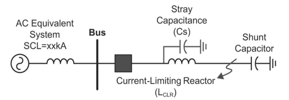
Figure 1. One-line Showing Reactor Limited Fault
2. Why It Matters
A breaker may satisfy the required interrupting current rating and still be unsuitable for clearing reactor-limited fault current. In these cases, the controlling duty is often the TRV and RRRV across the breaker after interruption, not simply the magnitude of fault current. If that duty is not specifically evaluated, the designated victim breaker may be misapplied even though the conventional short-circuit current check appears acceptable.
If the breaker is applied outside of its actual capability there is an increase in the risk of interruption failure, restrike, equipment damage, and reduced system reliability. For that reason, reactor-limited fault duty should be evaluated as a distinct breaker application problem using IEEE Std C37.011-2019 as guidance.
3. Reactor-Limited Fault Event Modeling
When a breaker clears a reactor-limited fault, the inherent TRV approximates a highly oscillatory, low-damped single-frequency waveform. Accurately assessing this physical behavior against standardized breaker capabilities requires a specific mathematical conversion:
- Physical to Standard Conversion:
The inherent TRV of a reactor-limited fault approximates a highly oscillatory 1-cosine wave reaching its peak at a physical time (T2). However, IEEE breaker ratings evaluate capabilities using standardized straight-line reference envelopes defined by an equivalent reference time (t3). To accurately compare the actual physical waveform to the breaker’s rated capabilities, the physical time-to-peak (T2) must be mathematically converted to the standard equivalent reference time (t3). This is achieved using a T2/t3 Conversion Multiplier found in IEEE Std C37.011 Table A.3. This specific multiplier is dictated by the circuit’s amplitude factor (kaf), defined as the ratio of the highest TRV peak to the peak value of the normal-frequency recovery voltage, which is typically evaluated at 1.9 for current-limiting reactors.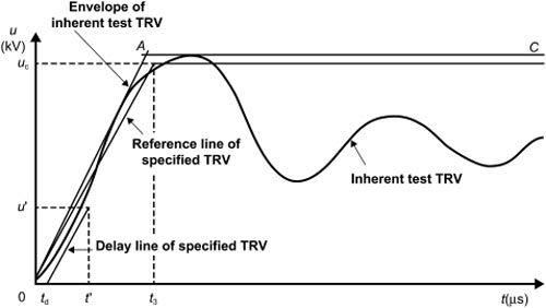
Figure 2. Inherent Test TRV With Two-Parameter Envelope
- First-Pole-to-Clear Factor (KPP):
The system grounding dictates the physical KPP factor (1.3 for effectively grounded systems or 1.5 for ungrounded systems) used to calculate the actual system TRV peak. While effectively grounded systems <100 kV physically experience a lower duty (KPP = 1.3), standard circuit breakers in this voltage class are universally type-tested to a baseline KPP of 1.5, providing an inherent margin of safety. - Source Contribution:
The total System TRV Peak (UC) is determined by summing the reactor’s high-frequency TRV contribution with the power-frequency recovery voltage contribution from the source side.
4. Device Verification Logic: Interpolating Enhanced Capabilities
The core function of a proper TRV assessment is comparing the calculated system TRV stresses with the duty-adjusted capabilities of the specified S1 (Cable) or S2 (Line) circuit breaker.
Because the reactor significantly reduces the available short-circuit current, the victim breaker is evaluated at a fraction of its maximum short-circuit rating. According to IEEE Std C37.011 Table 1, interrupting lower fault currents (e.g., T10, T30, T60 duties) grants the breaker enhanced TRV limits. An evaluation must calculate the Per Unit Fault Duty (ICLR/ISC) and interpolate the following standard multipliers:
- TRV Peak Voltage Multiplier (KUC): Scales up the allowable peak voltage limit based on the reduced thermal and dielectric stress of interrupting a lower fault current.
- Time-to-Peak Multiplier (Kt3): Scales down the allowed time-to-peak, mathematically elevating the allowable RRRV that the breaker can safely withstand.
A “PASS” condition indicates that the system’s calculated UC and equivalent t3 (RRRV) fall safely within the breaker’s duty-specific enhanced capability envelope. The VarStec Reactor-Limited Fault TRV & Breaker Duty Assessment Tool automatically applies these complex interpolations to instantly provide this PASS/FAIL result.
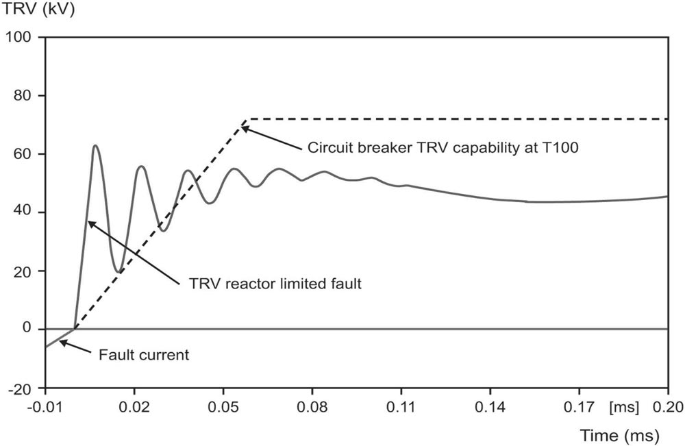
Figure 3. Calculated TRV of a Reactor Limited Fault
Without Added Capacitors
5. Navigating a “FAIL” Condition: TRV Mitigation Strategies
If the calculated transient duty exceeds the standard breaker’s enhanced limits, engineers must employ practical mitigation strategies to achieve a safe “PASS” condition.
Option 1: Specify a Definite-Purpose Circuit Breaker
Standard circuit breakers are tested for typical network faults. However, engineers can specify a “definite-purpose” circuit breaker designed and tested explicitly for fast TRV rise times in accordance with IEEE Std C37.06-2009. These breakers have higher inherent RRRV capabilities and can often clear reactor-limited terminal faults without additional mitigation equipment.
Option 2: Increase the Circuit Breaker Ratings
If the system TRV exceeds the boundary of the selected breaker, using a breaker with higher nominal ratings can resolve the issue:
- Higher Voltage Rating: Upgrading the voltage class (e.g., from 15.5 kV to 25.8 kV) inherently provides a much higher baseline TRV peak withstand capability.
- Higher Short-Circuit Rating: Upgrading the short-circuit current rating (e.g., from 12.5 kA to 40 kA) ensures the fault represents a much smaller percentage of the breaker’s total capability. This yields more favorable KUC and Kt3 multipliers, mathematically elevating both the permitted TRV Peak and RRRV.
Option 3: Add and Optimize a Surge Capacitor
When upgrading the breaker is cost-prohibitive, an effective economic alternative is adding a phase-to-ground surge capacitor. However, this introduces a physical trade-off: while adding capacitance slows the high-frequency transient and reduces the RRRV to a “PASS” condition, delaying the transient inherently gives the background power-frequency voltage more time to rise, thereby increasing the total combined TRV peak (UC). Arbitrarily sizing this capacitor can push the TRV Peak into a “FAIL” condition; therefore, the capacitor size must be carefully optimized to satisfy both parameters simultaneously.
Option 4: Combined Optimization
In severe applications where a “perfect” capacitor size cannot satisfy both the RRRV and TRV Peak limits, a combined approach is recommended: use a moderately sized surge capacitor to manage the RRRV, paired with a circuit breaker that possesses a higher short-circuit or voltage rating to safely absorb the elevated TRV peak.
6. Standards and Additional Resources
The calculations and methodologies described in this brief and utilized within the VarStec assessment tool strictly adhere to the following industry standards:
- IEEE Std C37.011-2019: IEEE Guide for the Application of Transient Recovery Voltage for AC High-Voltage Circuit Breakers.
- IEEE Std C37.04-2018: IEEE Standard for Ratings and Requirements for AC High-Voltage Circuit Breakers with Rated Maximum Voltage Above 1000 V.
- IEEE Std C37.06.1: IEEE Recommended Practice for Preferred Ratings for High-Voltage (> 1000 volts) AC Circuit Breakers Designated Definite Purpose for Fast Transient Recovery Voltage Rise Times.
7. Key Takeaways
Reactor-limited fault clearing subjects additional clearing duty on standard circuit breakers due to TRV rise times. Evaluating this duty requires a two-step, standards-based approach: first, mathematically translating the physical transient waveform into a standard equivalent reference time, and second, accurately interpolating the circuit breaker’s enhanced capability limits based on the reduced fault current.
Because standard breakers frequently fail this evaluation, designing a mitigation strategy, whether through specifying definite-purpose breakers, uprating breaker classes, or applying surge capacitors, is essential for safe and reliable substation design. The VarStec Reactor-Limited Fault TRV & Breaker Duty Assessment Tool eliminates the manual calculations required by IEEE standards, providing an immediate, defensible engineering analysis to ensure your equipment is safe and compliant
About the Author
Paul B. Steciuk is Co-Founder and President of VarStec Power Solutions and a subject matter expert in medium-voltage reactive compensation and power quality, specializing in the design, development, and manufacturing of fully integrated metal-enclosed capacitor banks and harmonic filter banks. His technical expertise spans the entire project scope, from initial harmonic and power system analysis through to the physical design, manufacturing, and final commissioning of specialized reactive compensation power equipment.
Before co-founding VarStec, Paul co-founded and led Northeast Power Systems, Inc. (NEPSI) for more than 25 years, supporting consultants, EPCs, utilities, and industrial users worldwide. He earned his degree in electric power engineering from Rensselaer Polytechnic Institute (RPI), began his career at Power Technologies, Inc. and Commonwealth Sprague Capacitor, Inc., and has authored more than 30 technical articles and white papers on reactive compensation, harmonic analysis, and harmonic filter applications.