
Medium-voltage switched shunt reactor bank for collector systems and other networks, intended to absorb cable or line charging vars, control voltage rise, and maintain acceptable system voltage during light-load operating conditions.
1. General
1.1 Scope of Work
This specification governs the design, manufacture, and testing of a medium-voltage switched shunt reactor bank. The reactor bank shall be provided as a fully integrated system, including all switching, protection, and control components. The unit shall be shipped completely assembled and factory-tested, requiring only field anchorage and connection to the primary and control circuits.
1.2 Ratings and Capacity
The shunt reactor bank shall provide a total three-phase reactive power rating of ______ kvar at a nominal voltage of ______ kV. The total capacity shall be divided into ______ switching steps of ______ kvar each.
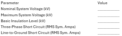
1.3 System Parameters
The equipment shall be designed for operation on a power system with the following characteristics:
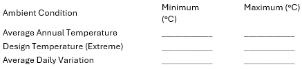
1.4 Environmental Design Criteria
The equipment shall be designed for continuous outdoor operation under the following ambient conditions:
1.5 Seismic Requirements
Equipment, internal supports, and anchorage shall be designed for seismic forces in accordance with the International Building Code (IBC) and ASCE 7, Chapter 13 (Nonstructural Electrical Components). Design shall be based on the following project-specific criteria:
- Risk Category: [_____]
- Seismic Design Category: [_____]
- Spectral Response (SDS): [_____]
- Spectral Response (SD1): [_____]
- Component Importance Factor (IP): [1.0] [1.5]
- Post-Earthquake Operability Required: [Yes] [No]
2. Product Certification and Listing
2.1 The shunt reactor enclosure system shall be Listed and Labeled by a Nationally Recognized Testing Laboratory (NRTL) to the following standards:
- United States: IEEE C37.20.3 (Standard for Metal-Enclosed Interrupter Switchgear).
- Canada: CSA C22.2 No. 31 (Switchgear Assemblies) or CSA C22.2 No. 190 (Capacitors and Reactors).
2.2 The shunt reactor bank control system shall be UL508A Certified for both Canadian and US products.
3. Compliance with Standard & Codes
3.1 The metal enclosed shunt reactor bank shall conform to or exceed the latest applicable requirements of the following standards and codes:
- IEEE C57.21-2021: Standard Requirements, Terminology, and Test Code for Shunt Reactors
- UL-508A: Standard for Industrial Control Panels
- IEEE C37.20.3 – 2023: Standard for Metal-Enclosed Interrupter Switchgear
- IEEE C37.20.4 – 2013: Standard for Indoor AC Switches (1kV to 38kV) For Use In Metal-Enclosed Switchgear
- IEEE C37.04-2018: Standard for Ratings and Requirements for AC High-Voltage Circuit Breakers with Rated Maximum Voltage Above 1000V
- IEEE C37.015 – 2017: Stand for the Application of Shunt Reactor Switching
- UL-50 & UL 50E: Enclosures for Electrical Equipment, Environmental Considerations
- ANSI Z535.4-2011: (R2023) Product Safety Signs and Labels
- NFPA 70 – 2023: Article 470 & 490 of the National Electrical Code
- ANSI C37.20.2: Guide for Enclosure Categories and Related Requirements
- NFPA 70-2023: Article 490: Equipment Over 1000 Volts, Nominal
4. Enclosure Construction
4.1 Manufacturing and Responsibility
The manufacturer of the enclosure shall also be the assembler of the shunt reactor bank. This integration is mandatory to ensure single-point accountability and total control over critical processes, including structural welding, surface preparation, and the application of the specified coating system.
4.2 Structural Design
- Configuration: The shunt reactor bank shall be a NEMA 3R, flush-door enclosure housing all necessary components, including controls, fuses, reactors, switches, and RC snubbers.
- Accessibility: All components shall be accessible and removable from the front or side of the enclosure.
- Materials: Enclosure walls and doors shall be fabricated from 11-gauge cold-rolled A60 galvannealed steel (or specify 12-guage stainless steel, type 304, 316, or 409).
- Roof: The roof shall be cross-kinked, half-gabled, or full-gabled to ensure positive watershed.
- Base: The enclosure base shall be constructed of C4x5.4 structural steel channel. Formed sheet-metal bases are prohibited.
- Lifting: Removable 1/2-inch steel lifting plates shall be provided at each corner.
4.3 Coating and Finish
The enclosure shall be finished with a high-performance, high-solids epoxy system. Interior and exterior surfaces shall be finished in ANSI 61 Gray.
- Surface Preparation: All surfaces shall be prepared per SSPC/AMPP (SP2, 3, 6, 7, 10, 11) or the paint manufacturer’s specific recommendations. Documentation of preparation procedures must be included in the submittal.
- Inaccessible Surfaces: Any surface rendered inaccessible after fabrication must receive the full coating system prior to assembly. These areas are classified as Zone 2A per SSPC.
- Performance Metrics: The total Dry Film Thickness (DFT) shall be 3.5 to 8.0 mils. The coating must meet the following:
- Salt Spray (ASTM B117): 5500 Hours (no face blistering).
- Humidity (ASTM D2247): 5500 Hours (no face corrosion/blistering).
- Gloss Retention (ASTM G53): >50% at 26 weeks (QUV-B).
- Elongation (ASTM D522): 14%.
- Adhesion (ASTM D4541): 2700 PSI.
- Fire Rating: NFPA Class A.
4.4 Doors and Access
- Design: Doors shall be flush-mounted (no overhanging sills) with heavy-duty stainless steel hinges and 3-point latching, pad-lockable handles.
- Safety Features: Doors providing access to high-voltage compartments shall include door stays and drip shields. Doors shall be removable only when in the open position.
- Internal Barriers: The load-interrupter switch compartment (if provided) shall feature an internal hinged protective barrier to prevent inadvertent contact with live terminals while allowing access to main fuses (if provided).
- Viewing Windows: Impact and UV-resistant wide-view windows shall be provided for the interrupter switch (if provided) to verify blade position, the fuse compartment (if provided), reactor terminals and RC Snubber compartment.
4.5 Ventilation and Thermal Management
- Louvers and Filtration: Ventilation louvers shall be equipped with 2-inch MERV 5 fiberglass filters. Filters must be replaceable while the bank is energized without exposure to live parts.
- Hardware: All fasteners and hardware, internal and external, shall be stainless steel. No externally accessible hardware shall support high-voltage components or operating mechanisms.
- Environmental Control: Thermostatically controlled strip heaters shall be provided in all non-ventilated compartments. Forced-air cooling fans shall be provided when required by thermal design.
- Calculations: Temperature rise calculations shall be provided by the manufacturer upon request.
4.6 Grounding and Labeling
- Ground Bus: A continuous 1/4″ x 2″ tin-plated copper ground bus shall span the full width of the enclosure.
- Safety Labels: Self-adhesive vinyl warning signs complying with ANSI Z535.4-2011 (R2023) shall be applied to each door.
- Nameplate: A riveted, anodized steel nameplate shall be provided, including:
- Nominal and Maximum System Voltage.
- BIL Rating.
- Reactive Power Rating.
- RC Snubber Details
- Instrument accuracy class.
5. Shunt Reactors
5.1 Dry-Type Shunt Reactors
For shunt reactor banks rated 15 kV (less than 110 kV BIL), reactors may be specified as dry-type with ratings up to 1000 kvar three-phase.
- Construction: Reactors shall be single-phase, iron-core units utilizing high-grade magnetic steel laminations.
- Windings and Insulation: All windings shall be based on manufacturers standard. The insulation system shall be rated for 220°C (Class R) with a designed temperature rise of 80°C over a 60°C ambient.
- Magnetic Design: To minimize gap magnetic losses and extraneous fields, a distributed gap design shall be utilized. All core gaps shall be cemented to minimize audible noise levels.
- Processing: The reactor assembly shall undergo Vacuum Pressure Impregnation (VPI) for mechanical and environmental integrity.
- Voltage Rating: The design shall support continuous operation at 10% over-voltage.
5.2 Liquid-Filled Shunt Reactors
For shunt reactor banks rated up to 38 kV (200 kV BIL and lower), reactors may be specified as liquid-insulated.
- Insulating Fluid: Units shall be mineral oil-filled in accordance with the latest edition of the NEC. High fire-point fluids (e.g., RTemp, FR3) may be provided as an option and must be UL Listed and Factory Mutual (FM) Approved.
- Bushings: Reactors shall be equipped with high-voltage bushings and a fully rated neutral bushing to allow for both grounded and ungrounded operation.
- Thermal Performance: Winding temperature rise shall not exceed 65°C (by resistance test), based on an average ambient of 30°C over 24 hours (maximum 40°C).
- Audible Noise: Sound levels shall meet requirements defined in IEEE C57.21 (formerly ANSI C57.12.21).
- Windings: High-voltage windings shall be copper with high-quality paper insulation between layers; no exceptions.
5.3 Liquid-Filled Tank Construction
- Mechanical Integrity: The tank and components shall withstand pressures 25% greater than the operating design value without permanent deformation.
- Materials: The tank shall be constructed from minimum 1/4-inch carbon steel plate with a fully welded 3/8-inch thick cover. All seams and joints shall be continuously welded and reinforced with external sidewall braces.
- Leak Testing: Radiator assemblies and the main tank shall receive individual pressure checks. A final six-hour leak test is required after the core and coil are tanked and the assembly is welded complete.
- Standard Fittings: Each tank shall be equipped with a drain and filter valve, a sampling device, and a 10 PSI self-resealing pressure relief valve.
5.4 Optional Liquid-Filled Features
The following features may be specified for liquid-filled units:
- Externally operated, padlockable under-oil disconnect switch.
- Dial-type gauges for liquid temperature, liquid level, and pressure/vacuum.
- Sudden Pressure Relief Device (PRD) equipped with alarm contacts.
6. Load Interrupter / Air Disconnect Switch
6.1 Switching Technology
The shunt reactor bank shall be equipped with an external, chain-operated load-interrupting switch. Current interruption shall be achieved through a dual arc-extinguishing system utilizing a combination of auto-pneumatic air-blast and hard-gas nozzle principles.
6.2 Electrical Ratings
- Continuous Current: The switch shall be rated for a minimum of 135% of the bank’s nominal current rating.
- Momentary Rating: The switch shall have a 40-kA RMS asymmetrical momentary (withstand) rating.
6.3 Safety and Interlocking
- Operational Interlock: The air disconnect switch shall be mechanically or electrically interlocked with the vacuum switches/Breaker to prevent the disconnect from being operated while the reactor stage(s) are energized.
- Security: The operating mechanism shall be padlockable in both the fully open and fully closed positions.
6.4 Enclosure and Compartmentalization
- Isolation: The air disconnect switch shall be housed in a dedicated compartment, physically isolated from the shunt reactor and low-voltage control compartments by grounded steel barriers.
- Secondary Protection: In addition to the exterior enclosure door, an internal protective screen or hinged barrier shall be provided. This screen must be in place to prevent accidental contact with live parts when the exterior door is opened.
7. Ground Switch
7.1 Functional Requirements
An externally operated ground switch shall be provided to effectively ground the load-side terminals of the air-interrupter switch. This ensures that the shunt reactor and associated internal components are discharged and maintained at ground potential during maintenance.
7.2 Security and Compliance
- Locking: The ground switch operating mechanism shall be padlockable in both the fully open and fully closed positions.
- Standards: The switch shall be designed and tested in accordance with applicable ANSI/IEEE standards. Certified test reports shall be furnished to the owner upon request.
7.3 Safety Interlocking
The ground switch shall be mechanically interlocked with the main air-interrupter switch. This interlock must positively prevent the ground switch from being closed whenever the air-interrupter switch is in the closed position, and conversely, prevent the air-interrupter switch from closing while the ground switch is engaged.
8. Main Incoming Fuses
8.1 Functional Configuration
The shunt reactor bank shall be equipped with medium-voltage current-limiting fuses. The fuses shall be electrically positioned on the load side of the air-disconnect switch to provide primary overcurrent and short-circuit protection for the entire reactor assembly.
8.2 Safety and Accessibility
- Isolation: The fuses shall be housed in a dedicated compartment, physically separated from high-voltage line-side components.
- Maintenance Access: The fuse compartment shall be designed such that the fuses are accessible only when the main air-disconnect switch is in the open (de-energized) position.
- Personnel Protection: When the disconnect switch is open and the fuse compartment door is accessed, the fuses shall be completely isolated from any remaining upstream live parts by grounded metal barriers.
9. Shunt Reactor Switches
9.1 Switching Technology
Each shunt reactor stage shall be controlled by vacuum switches, vacuum contactors, or and SF6 switch specifically rated for shunt reactor switching duties.
- Transient Mitigation: Where application-specific analysis dictates, RC snubbers shall be integrated to limit High Transient Recovery Voltage (TRV) across the switching device.
- Protection: The switching assembly shall be designed to protect the reactors from damage resulting from switch restrike or re-ignition during opening operations.
9.2 Control Interface and Logic
The reactor switches shall be provided with a three-position ON/OFF/AUTO selector interface:
- AUTO: The switching device shall operate based on external signals from the digital power factor controller or other specified automated supervisory system.
- ON/OFF (Manual): The manual positions shall provide a direct hardware override, forcing the switch to the commanded state regardless of the automated controller’s output signal.
9.3 System Interlocking
For personnel safety and equipment protection, the reactor switches shall be integrated into the bank’s overall interlocking scheme:
- Operational Sequence: The switches shall be interlocked with the main air-disconnect switch and the ground switch to ensure they cannot be closed unless the disconnect is closed and the ground switch is open.
- De-energization: The logic shall ensure the reactor switches are tripped or locked out whenever the main disconnect is opened.
10. Lightning / Surge Arresters
10.1 Protective Classification
The shunt reactor bank shall be equipped with Station Class surge arresters to provide primary overvoltage protection against atmospheric lightning strikes and system switching transients.
10.2 Sizing and Coordination
- Responsibility: The specific voltage and energy discharge ratings of the arresters shall be determined and recommended by the shunt reactor manufacturer.
- Selection Criteria: The selection shall ensure proper insulation coordination with the reactor’s BIL rating and the specific grounding configuration (solidly grounded, ungrounded, or resistance grounded) of the host utility or facility power system.
11. Phase and Ground Bus
11.1 Material and Plating
All primary phase and ground busbars shall be fabricated from high-conductivity copper and tin-plated at all contact surfaces and throughout their length to ensure maximum conductivity and long-term corrosion resistance.
11.2 Bolted Connections and Hardware
All bus-to-bus bolted joints shall be secured using 3/8” – 16 stainless steel hardware to ensure consistent contact pressure. Each bolted connection shall include:
- One (1) stainless steel bolt.
- Two (2) stainless steel flat washers (one under the bolt head, one under the nut).
- One (1) stainless steel split lockwasher (positioned between the flat washer and the nut).
- One (1) stainless steel nut.
11.3 Electrical and Thermal Ratings
- Current Density: The bus system shall be sized such that the current density does not exceed 1200 Amps per square inch at the maximum continuous rating of the bank.
- Expansion Capability: Where future expansion is specified or required, the buswork shall be rated for the maximum ultimate capacity of the shunt reactor bank.
11.4 Mechanical Strength and Short-Circuit Withstand
The busbars, primary interconnections, and their associated supports (insulators) shall be mechanically engineered to withstand the electromagnetic stresses associated with the specified peak available short-circuit current at the terminals of the shunt reactor bank.
12. Keyed Interlock System
12.1 General Requirements
The shunt reactor bank shall be equipped with a comprehensive trapped-key interlock system. This system is mandatory to enforce a strict safety sequence, preventing unauthorized entry and ensuring that all high-voltage components are de-energized and grounded before enclosure doors can be opened.
12.2 System Configuration and Hardware
- Mounting: Keyed interlocks shall be mounted behind the enclosure doors, with only the key cylinders protruding through the door face.
- Environmental Protection: All lock cylinders shall be equipped with stainless steel spring-loaded covers to protect against debris and moisture.
- Design Restrictions: The system shall allow all doors to be opened simultaneously once the sequence is initiated. Master key interchanges and externally mounted (surface-mounted) interlocks are prohibited.
12.3 Sequential Interlock Logic
The interlock scheme shall encompass the upstream protective device (where applicable), the main air-disconnect switch, the ground switch, and all enclosure doors. The mandatory operating sequence shall be as follows:
- De-energization of Stages: Manually switch all shunt reactor stages to the OFF position using the local ON/OFF/AUTO control switches.
- Isolation and Grounding: Use the primary “A1” key to unlock the air-disconnect switch. Open the air-disconnect switch and subsequently close the mechanically interlocked ground switch.
- Key Release (Grounding): Remove the “A2” key from the ground switch. The removal of this key shall mechanically lock the ground switch in the CLOSED (grounded) position.
- Primary Access: Use the “A2” key to unlock the Air-Disconnect Switch External Compartment Door. Upon opening, the “A3” key shall be released from the door lock.
- Note: Access to the switch terminals remains blocked by the internal hinged barrier. If specified, this internal barrier can be further interlocked with the upstream feeder breaker.
- Sequential Door Release: * Use the “A3” key to open the first reactor compartment door, which releases the “A4” key.
- Use the “A4” key to open the subsequent door, releasing the next key in the sequence (if applicable).
- Final Access: This “daisy-chain” procedure shall be repeated until all enclosure doors are unlocked and open.
13. Controls
13.1 Control Compartment and Isolation
- Integration: The control compartment shall be an integral part of the enclosure; externally mounted control cabinets are prohibited.
- Isolation: All low-voltage controls shall be physically isolated from high-voltage compartments via grounded steel barriers. Controls must remain safely accessible while the shunt reactor bank is energized.
- Entry and Wiring: The compartment shall facilitate top or bottom entry for customer control wiring without requiring access to medium-voltage sections. All control wiring traversing high-voltage areas must be enclosed in metal conduit or integrated wire troughs.
- Ergonomics: The compartment shall feature a swing-out dead-front panel to provide rear access to panel-mounted components and wiring.
13.2 Control Power and Protection
- Source: A dry-type Control Power Transformer (CPT) shall be provided, connected between phases B and C. The CPT shall include both primary and secondary overcurrent protection.
- Circuit Protection: The complete control circuit shall be protected by a main circuit breaker. All key control components shall be protected and switched using UL-rated control power circuit breakers.
- Compliance: The control system assembly shall be listed under UL 508A for Industrial Control Panels.
13.3 Automation and Switching Logic
- Controller: The bank shall include a digital controller capable of automatically switching reactor stages based on voltage, power factor, or var flow.
- Stage Interface: Each stage shall be equipped with:
- An ON/OFF/AUTO selector switch.
- Visual indicators for Stage ON (Green) and Stage OFF (Red).
13.4 Enclosure Amenities
- Lighting: Integrated lighting shall be provided for the reactor, control, and air-disconnect switch compartments, operated by a master switch in the control compartment.
- Convenience: A 20-amp GFI duplex outlet shall be installed within the control compartment.
13.5 Advanced Metering (Optional)
When specified, a three-phase digital power meter shall be provided, receiving signals from three (3) current transformers and two (2) potential transformers. The meter shall be factory-programmed to monitor and log:
- Instantaneous Values: Voltage, current, real/apparent/reactive power, and power factor (per phase and average).
- Power Quality: Voltage and current unbalance, frequency, and Total Harmonic Distortion (THD) through the 50th harmonic.
- Energy Accumulation: Imported, exported, absolute, and net kWh/kVARh, and accumulated kVAh.
- Demand: Sliding window, predicted, and thermal demand for kW, kVAR, kVA, and average current.
- Min/Max Tracking: Non-volatile storage of minimum and maximum values for all primary electrical parameters.
- I/O: Four (4) programmable digital outputs for relay control based on measured setpoints.
14. Supplier Quality and Qualifications
14.1 Quality Management System
The supplier shall maintain a formal quality management system with third-party certification by an internationally recognized accreditation body to ISO 9001:2015 (or the latest revision). A valid copy of the ISO certification shall be submitted with the quotation.
14.2 Product Certification and Listing
The supplier shall be authorized by a Nationally Recognized Testing Laboratory (NRTL) to apply certification labels to the equipment.
- Enclosure and Assembly: The shunt reactor bank shall be compliant with IEEE C37.20.3 (Standard for Metal-Enclosed Interrupter Switchgear).
- Components: The assembly shall meet the requirements of CSA C22.2 No. 190 (Capacitors and Reactors) and CSA C22.2 No. 31 (Switchgear Assemblies).
14.3 Control Panel Compliance
The supplier shall maintain factory certification through periodic inspections by an NRTL (such as UL or TÜV) to apply UL 508A and C-UL labels to their industrial control panels. A copy of the current certification shall be provided with the quotation.
14.4 Engineering Proficiency
To ensure technical competence in medium-voltage reactive compensation, the supplier shall maintain a staff of experienced, Licensed Professional Engineers (PE). These individuals shall hold degrees in Electrical Power Engineering, preferably with advanced degrees, as evidence of their proficiency in power system design and analysis.
14.5 References and Experience
The supplier shall provide a reference list of customers for whom they have provided similar medium-voltage metal-enclosed equipment. This list shall include contact information to facilitate reference checks and shall be provided at the time of quotation.
14.6 Factory Audits
The supplier shall allow the customer to perform factory audits at the manufacturing facility. Such audits shall occur at a mutually agreed-upon date and time between the customer and the supplier to verify manufacturing processes and quality control measures.
15. Submittals and Documentation
15.1 Approval Drawing Package
Following the issuance of a purchase order, the supplier shall submit a complete set of approval drawings for review. Fabrication shall not commence until the customer has provided written approval of the submittal package.
15.2 Submittal Content
The submittal package shall be comprehensive and include, at a minimum, the following technical documentation:
- Installation Instructions: Detailed procedures for site handling, leveling, and assembly.
- Schematic Diagrams: Complete Single-Line and Three-Line diagrams illustrating the primary power circuit, switching logic, and protection schemes.
- Plan View and Section Drawings: Detailed drawings showing the enclosure footprint, anchoring requirements (pad details), and specific locations for top or bottom cable entry.
- Component Layout: Internal elevation drawings identifying the physical arrangement and clearances for all major components, including reactors, switches, fuses, and control structures.
- Technical Data Sheets: Manufacturer-published specifications and data sheets for all internal primary components (reactors, switches, arresters, fuses, and controllers).
- Bill of Materials (BOM): A complete material listing identifying part numbers, ratings, and quantities for all system components.
15.3 Operation and Maintenance (O&M) Manuals
Final “As-Built” documentation, including certified test reports and localized O&M manuals, shall be provided with the equipment shipment.
16. Bid Requirements
16.1 Inspection and Test Plan (ITP)
The supplier shall submit a comprehensive Inspection and Test Plan (ITP) with the bid. This document must detail all proposed factory production tests, specialized type tests, and final certifications. The ITP shall include a definitive schedule for the submission of all test reports, indexed from the date of award.
16.2 Supplier Document List (SDL)
A Supplier Document List (SDL) shall be provided, identifying all submittal and close-out documentation to be furnished (e.g., approval drawings, O&M manuals, certified test reports). The SDL must include a submittal schedule expressed in weeks after the date of award.
16.3 Statement of Exceptions
The supplier shall explicitly state all technical or commercial exceptions to this specification within the bid proposal. If no exceptions are taken, the supplier must provide an affirmative statement that the proposal is in full compliance with the specification as written.
16.4 Supplier Qualification
The supplier must complete and include the attached Supplier Qualification Form with their formal quotation. Failure to provide this completed form at the time of bid submission shall be grounds for immediate rejection of the proposal.
16.5 Warranty and Field Service
The supplier shall provide written details regarding available extended warranty options and field service agreements. These policy documents must be included in the bid package to allow for evaluation of long-term support capabilities.
16.6 Quality Policy
The supplier’s formal, written Quality Policy shall be submitted with the bid as evidence of the manufacturer’s commitment to quality assurance and continuous improvement.
16.7 Shipping Terms
All quotations shall be provided on an F.O.B. Factory, Freight Allowed basis, unless otherwise specified in the project-specific RFP.
17. Testing and Test Reports
17.1 General Requirements
The manufacturer shall perform comprehensive testing on all components and the completed assembly in accordance with applicable IEEE, ANSI, and NEMA standards. A detailed Inspection and Test Plan (ITP) shall be provided with the bid. Fabrication and assembly shall be governed by this ITP, and all results shall be documented in a certified test report.
17.2 Dielectric and Insulation Testing
The fully assembled unit shall undergo dielectric testing to verify insulation integrity under various operational configurations (e.g., main switch open/closed, stage switches open/closed).
- Power-Frequency Withstand: Conducted per IEEE C37.20.3 and IEEE Std 4.
- Lightning-Impulse Withstand (BIL): Conducted in accordance with IEEE C37.57 and IEEE C37.20.3, Table 1.
17.3 Component-Specific Testing
- Air Disconnect Switch: Shall include Contact Resistance (Ductor) testing, a 1-minute Hi-Pot test at standard voltage, and mechanical operation verification.
- Shunt Reactors: Shall be tested for inductance accuracy, winding resistance, and insulation integrity.
- Instrument Transformers (CTs/PTs): Shall undergo Turns Ratio, Polarity, Insulation (Megger), and Excitation testing per IEEE C57.13.
- Surge Arresters: Verification of Reference Voltage, Residual/Discharge Voltage, Partial Discharge, and Power Frequency withstand.
- Capacitors (if applicable): Shall include leak testing, capacitance and loss (tan delta) measurement, discharge resistor verification, and high-voltage ground testing.
17.4 Advanced Switching Device Testing
- Southern States CapSwitcher®: Testing shall include Hi-Pot, Timing, Contact Resistance, Heater Wattage, SF6 Leak Check, Gas Density Switch verification, and Slow-Close operational checks.
- SF6 Circuit Breakers: Shall undergo mechanical operation cycles, Power-Frequency Withstand, Contact Resistance, and Operating Time (Opening/Closing) benchmarks.
17.5 Control and Protection Verification
All relays, meters, and control devices shall be programmed, calibrated, and functionally tested prior to shipment.
- Documentation: Final relay settings and calibration constants shall be documented and included in the O&M manuals.
- Wiring: A point-to-point continuity check of all control wiring shall be performed.
17.6 Final Inspection and Witnessing
- Assembly: The equipment shall be fully assembled and undergo a final mechanical and electrical integration test prior to shipment.
- Certified Reports: All test reports must be signed by a Professional Engineer or Quality Manager and approved by the customer before the equipment leaves the factory.
- Witness Testing: The customer reserves the right to witness any or all tests at the manufacturer’s facility at no additional contract cost. The manufacturer shall provide a minimum of 15 working days notice prior to the commencement of witnessed testing.
18. Acceptable Product and Suppliers
18.1 Warranty Requirements
The supplier shall provide a standard warranty for all equipment and components for a period of 18 months from the date of shipment or 12 months from the date of energization, whichever occurs first. In addition to the standard warranty, the supplier must have extended warranty programs available for purchase at the time of the bid.
18.2 Testing Capabilities
The supplier must demonstrate the facility infrastructure and technical expertise required to meet all primary, dielectric, and functional testing requirements specified in Section 4.10 (Testing and Test Reports).
18.3 Quality System Certification
The manufacturer shall maintain a current ISO 9001 certification. This certification must be issued by an independent, ISO-accredited auditing firm. A valid copy of the ISO 9001 certificate shall be included as a mandatory component of the bid package.
18.4 Manufacturer Experience and References
The supplier shall demonstrate that they are a regular, established manufacturer of medium-voltage automatic metal-enclosed shunt reactor banks. To verify technical proficiency and product reliability, the following shall be provided upon request:
- Product Literature: Formal technical specifications and brochures detailing the manufacturer’s shunt reactor product line.
- Reference List: A list of customers and projects involving the successful installation and operation of similar metal-enclosed reactive compensation systems.
18.5 Acceptable Manufacturer and Product:
VarStec Power Solutions
Info@VarStec.com
VarStec.com
- 1. General
- 2. Product Certification and Listing
- 3. Compliance with Standard & Codes
- 4. Enclosure Construction
- 5. Shunt Reactors
- 6. Load Interrupter / Air Disconnect Switch
- 7. Ground Switch
- 8. Main Incoming Fuses
- 9. Shunt Reactor Switches
- 10. Lightning / Surge Arresters
- 11. Phase and Ground Bus
- 12. Keyed Interlock System
- 13. Controls
- 14. Supplier Quality and Qualifications
- 15. Submittals and Documentation
- 16. Bid Requirements
- 17. Testing and Test Reports
- 18. Acceptable Product and Suppliers