
A standards-based evaluation of close-in fault transient discharge duty, including victim breaker capability and the application of transient limiting inductors (TLIs) in accordance with applicable IEEE criteria.
Brief No.: VEB-008
Category: Equipment Design / Power Quality / Capacitor Banks / Transients
1. Introduction
While the transient stresses associated with capacitor bank energization, namely inrush current, primarily affect the dedicated capacitor switching device, a different transient condition can arise when a nearby fault occurs. If a permanent fault exists on an adjacent bus or feeder during a clearing or reclosing event while a capacitor bank remains energized, the charged bank can discharge into that fault through a very low-impedance path. This produces a large, high-frequency, high-magnitude transient discharge current, known as outrush current, that places severe mechanical and electrical stress on the circuit breaker. From the breaker’s perspective, this duty closely resembles capacitor bank inrush.
In this scenario, the breaker exposed to this duty is not the capacitor switching device itself, but an adjacent line, feeder, or bus-tie breaker, referred to here as the “Victim Breaker. Because these breakers are often general-purpose substation breakers and not specifically selected for capacitor switching duty, they may be exposed to transient currents that exceed their capabilities. With only a small amount of inductance between the energized capacitor bank and the fault, the resulting outrush current can reach tens of kiloamperes at frequencies of several kilohertz.
The ability of a Victim Breaker to withstand this duty depends on the interrupter technology, whether Vacuum, SF6, or Oil, and on its capacitive switching classification, such as C0, C1, or C2, as established by IEEE Std C37.04-2018. This VarStec Engineering Brief outlines the standards-based evaluation criteria for outrush events, drawing on the foundational application guidelines of IEEE Std C37.012-2022 and the transient analysis and mitigation frameworks detailed in IEEE PES-TR16, and explains why this analysis is an essential part of VarStec’s System-Fit™ approach to capacitor bank design.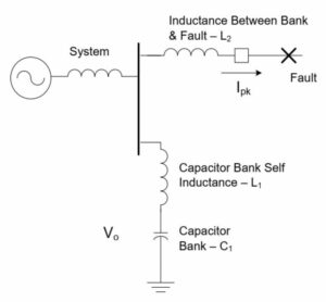
2. Why It Matters
When a Victim Breaker closes into a fault with significant charged capacitance behind it, the transient discharge current is superimposed on the system’s power-frequency fault current. If the resulting peak current and frequency exceed the mechanical and electrical capabilities of the circuit breaker, the consequences can be catastrophic.
For legacy bulk oil circuit breakers, the incredibly fast rate-of-change of the outrush current (di/dt) generates hydraulic shock waves within the incompressible oil medium. These shock waves can physically shatter the interrupter nozzles, crack stationary contacts, or destroy the insulating chamber entirely. For modern Vacuum and SF6 breakers, while they are not as sensitive to shock waves, an outrush current that exceeds the device’s peak making capability can result contact erosion or welding. Consequently, ensuring that all substation breakers are properly rated for potential outrush duty, or deploying appropriate mitigation, is vital for substation safety and reliability.
3. Technical Classification of Outrush Conditions:
To properly evaluate outrush duty, the power system parameters governing the discharge loop must be accurately modeled.
3.1 The Discharge Loop and Substation Configuration
The severity of the outrush current is determined by the total capacitance discharging into the fault and the total loop inductance between the capacitor bank and the fault location. This total loop inductance includes the capacitor bank’s self-inductance, the buswork, and any series reactors. Furthermore, the substation’s physical configuration dictates the worst-case capacitance. A single-ended substation relies solely on the local capacitor banks, while a double-ended substation with a closed bus tie can introduce additional parallel capacitance from an alternate source, substantially increasing the transient discharge duty.
3.2 Calculating Peak Outrush Current (Ipeak) and Frequency (f)
The analytical formulas for calculating the peak outrush current and its natural frequency are established in IEEE Std C37.012-2022 and IEEE PES-TR16. The VarStec Capacitor Bank Outrush & Close-in Fault Analysis tool automates these calculations, strictly adhering to IEEE guidance by applying standard safety multipliers for system overvoltage and the capacitor’s maximum positive tolerance. This provides the worst-case Peak Outrush Current (Ipeak) and Outrush Frequency (If outrush) to be evaluated against the Victim Breaker’s ratings,.
4. Device Technologies, Classifications, and Evaluation Criteria
Evaluating the calculated outrush stresses against the Victim Breaker’s capability is highly complex, as the pass/fail criteria differ vastly depending on the breaker’s technology and its restrike probability class.
4.1 Modern Circuit Breakers (Vacuum and SF6)
Extensive testing and decades of field experience have proven that Vacuum and SF6 interrupters are largely immune to the hydraulic shock wave damage that plagued older technologies. As defined in IEEE Std C37.012-2022 and IEEE PES-TR16, and enforced by the VarStec analysis tool, there is generally no specific upper limit for the outrush frequency product (I × f) for these modern devices.
Instead, the evaluation focuses strictly on the Peak Outrush Current:
- Class C1 and C2 (Definite Purpose): For these breakers, the calculated peak outrush current must not exceed the device’s Rated Closing and Latching Capability (Peak Making Current). Under IEEE Std C37.04-2018, this is standardly calculated as 2.6 × the Rated Symmetrical Short-Circuit Current.
- Class C0 (General Purpose): To prevent mechanical failure in general-purpose devices, the standard imposes a stricter limitation. The peak outrush current must not exceed the lesser of 1.41 × Rated Short-Circuit Current or 50 kA peak.
4.2 Legacy Circuit Breakers (Oil)
Because oil circuit breakers are shock-wave limited, their evaluation must consider both the peak current magnitude and the transient frequency. The VarStec tool evaluates this using the Outrush Frequency Product (I × f) Verification Criteria:
- Class C0 (General Purpose Oil Breakers): Per IEEE Std C37.04-2018, the product of the inrush/outrush current peak and frequency must not exceed a strict limit of 20,000 kA·Hz.
- Class C1 and C2 (Definite Purpose Oil Breakers): The calculated (I × f) product must not exceed the specific tested capability defined by the device’s nameplate (Rated Inrush Current × Rated Inrush Frequency). In the absence of specific nameplate data, a historical default limit of 85,000 kA·Hz is applied per IEEE PES-TR16.
5. Mitigation Strategies for Excessive Transient Duties
When the VarStec tool identifies a “FAIL” condition, meaning the calculated transient discharge duty exceeds the mechanical or frequency withstand capabilities of the specified Victim Breaker, two primary mitigation strategies can be employed.
5.1 Add Inductance (Install Transient Limiting Inductors)
Installing a Transient Limiting Inductor (TLI), or outrush reactor, in series with the capacitor bank is the most common method to mitigate outrush. By artificially increasing the total loop inductance between the capacitor bank and the fault, the Peak Outrush Current magnitude and the Transient Frequency seen by the Victim Breaker are both directly reduced to safe levels.
5.2 Upgrade the Victim Breaker
If adding a TLI is undesirable due to space, cost, or secondary TRV concerns, the alternative is to upgrade the Victim Breaker itself. Replacing an outdated Class C0 or Oil circuit breaker with a modern Vacuum or SF6 Class C2 circuit breaker provides a significantly higher Rated Closing and Latching Capability and eliminates the restrictive (I × f) shock wave limits, allowing the device to safely withstand the unmitigated outrush duty.
6. Engineering Considerations
System Grounding
When evaluating capacitor bank outrush duty, the grounding of the capacitor bank should also be considered. For ungrounded capacitor banks, which are common throughout the 2.4 kV to 38 kV voltage range, a remote external fault must generally be either a three-phase fault or a phase-to-phase fault in order to establish a closed-loop discharge path for the fault. In many substations, feeders are composed of cables rather than overhead line, and the most likely fault type is phase-to-ground as each phase is surrounded by a ground shield. Under that condition, little to no outrush current would be expected. As a result, the practical likelihood of a severe outrush event may be materially lower than a purely theoretical worst-case evaluation would suggest. For a phase-to-phase fault, the outrush current is equal to square root of 3 divided by 2 times the corresponding three-phase fault value.
That said, grounding alone should not be used to dismiss the need for analysis. The decision to mitigate, or not mitigate, the condition still requires engineering judgment based on the substation configuration, feeder construction, operating philosophy, and the Owner’s tolerance for risk. VarStec evaluates both the theoretical duty and the realistic fault exposure as part of its System-Fit™ design approach.
Transient Inrush Reactors Versus Outrush Reactors
Transient inrush current and close-in fault outrush current are related, but they are not governed by the same inductive path. Inrush current is driven primarily by back-to-back switching in multistage capacitor banks and is limited by the inductance between stages, including any transient inrush reactors. Outrush current, by contrast, occurs when an energized capacitor bank discharges into a nearby fault and is limited by the inductance in the discharge path between the capacitor bank and the fault location.
For this reason, a dedicated outrush reactor directly reduces close-in fault discharge duty, while a transient inrush reactor in a multistage bank contributes only partially. For example, in a three-stage bank with identical stage ratings, only about one-third of the per-stage transient inrush reactor inductance effectively contributes to limiting outrush duty. This distinction is important. A bank that is adequately protected against switching inrush is not automatically protected against close-in fault outrush.
There is an economic tradeoff among point-on-wave switching devices (using ABB VD4-CS), pre-insertion switching devices (Using Southern States CapSwitcher), transient inrush reactor cost, and dedicated outrush reactor cost, or upgrading the substation feeder breakers. These factors are evaluated together as part of VarStec’s System-Fit™ design approach.
Point-on-Wave and Pre-Insertion Resistor Switching
Switching technology must also be evaluated carefully in the context of both inrush and outrush performance. Point-on-wave switching devices, such as the ABB VD4-CS, and pre-insertion resistor switching devices, such as the Southern States CapSwitcher, are often selected because they are highly effective at controlling capacitor energization transients. However, their benefit for switching inrush should not be assumed to provide the same benefit for close-in fault outrush.
Pre-insertion resistors do not provide meaningful outrush limiting because they are only in the circuit during the capacitor energization process and are not part of the discharge path during an external fault. Similarly, point-on-wave switching often eliminates the need for transient inrush reactors at the capacitor switching device. While that may be beneficial for energization duty and overall project cost, it also leave less inductance in the discharge loop and therefore results in higher calculated outrush duty at the Victim Breaker. For this reason, VarStec evaluates switching technology as part of the complete substation design, balancing inrush performance, outrush performance, breaker duty, and total project cost.
Harmonic Filter Reactors
For harmonic filter banks, the tuning reactor provides another important consideration. In addition to harmonic filtering, resonance control, reactive compensation, and switching transient mitigation, the series reactor in a harmonic filter branch adds substantial inductance to the discharge loop. That inductance is typically much greater than what is present in a plain capacitor bank and therefore has a strong current-limiting effect on close-in fault outrush.
As a result, outrush duty is not a concern for harmonic filter banks. In nearly all practical cases, the tuning reactor impedance is high enough that close-in fault outrush does not become a limiting design issue. Even so, the duty should still be verified as part of the overall study, particularly where multiple banks, bus ties, or unusual substation configurations.
6. Standards and Additional Resources
- IEEE Std C37.012-2022: IEEE Guide for the Application of Capacitive Current Switching for AC High-Voltage Circuit Breakers Above 1000 V. Provides the theory of capacitive outrush, defines the risks to “hidden” circuits, and details the di/dt capabilities of modern versus legacy interrupters.
- IEEE Std C37.04-2018: IEEE Standard for Ratings and Requirements for AC High-Voltage Circuit Breakers with Rated Maximum Voltage Above 1000 V. Establishes the continuous, short-circuit, and close-and-latch ratings, as well as the defining parameters for Class C0, C1, and C2 switching classifications.
- IEEE PES-TR16: Transient Limiting Inductor Applications in Shunt Capacitor Banks. Provides detailed guidance on calculating outrush current, the historical context of I × f limits for oil breakers, and the practical sizing of TLIs.
7. Key Takeaways
Capacitor bank outrush current is a severe, high-frequency transient that endangers not the capacitor switch itself, but the surrounding feeder, line, and bus-tie breakers on the substation bus. Relying on simple rules of thumb is dangerous, as the pass/fail criteria change drastically depending on whether a breaker utilizes Oil, Vacuum, or SF6 technology, and whether it holds a C0, C1, or C2 classification.
VarStec’s System-Fit™ design approach ensures that no piece of equipment is evaluated in isolation. The VarStec Capacitor Bank Outrush & Close-in Fault Analysis Tool allows engineers to assess single-ended and double-ended substation configurations, automate the underlying calculations, apply the correct breaker-specific rating criteria, and verify the selected Victim Breaker against the applicable IEEE limits. This integrated approach helps ensure that any required Transient Limiting Inductors (TLIs) or breaker upgrades are properly sized for a safe, reliable, and standards-compliant substation design.
About the Author
Paul B. Steciuk is Co-Founder and President of VarStec Power Solutions and a subject matter expert in medium-voltage reactive compensation and power quality, specializing in the design, development, and manufacturing of fully integrated metal-enclosed capacitor banks and harmonic filter banks. His technical expertise spans the entire project scope, from initial harmonic and power system analysis through to the physical design, manufacturing, and final commissioning of specialized reactive compensation power equipment.
Before co-founding VarStec, Paul co-founded and led Northeast Power Systems, Inc. (NEPSI) for more than 25 years, supporting consultants, EPCs, utilities, and industrial users worldwide. He earned his degree in electric power engineering from Rensselaer Polytechnic Institute (RPI), began his career at Power Technologies, Inc. and Commonwealth Sprague Capacitor, Inc., and has authored more than 30 technical articles and white papers on reactive compensation, harmonic analysis, and harmonic filter applications.
- 1. Introduction
- 2. Why It Matters
- 3. Technical Classification of Outrush Conditions:
- 4. Device Technologies, Classifications, and Evaluation Criteria
- 5. Mitigation Strategies for Excessive Transient Duties
- 6. Engineering Considerations
- Transient Inrush Reactors Versus Outrush Reactors
- 6. Standards and Additional Resources
- 7. Key Takeaways
- About the Author