
A practical guide to split-wye neutral current detection in medium-voltage power capacitor banks and harmonic filter banks, including what it is, why it is used, and how to apply and set the protection relay.
Brief No.: VEB-002
Category: Protection / Blown Fuse Detection / Capacitor Banks / Harmonic Filter Banks
1. Introduction
Split-wye neutral current detection is one of the most widely used unbalance protection methods applied on medium-voltage power capacitor banks and harmonic filter banks. It is used to detect the loss of capacitance caused by fuse operation or other internal bank unbalance conditions that can create harmful overvoltage on remaining capacitor units and, in filter applications, shift the tuning characteristics of the bank. Because this protection method is widely specified and widely applied, it is important for engineers, consultants, and users to understand how the scheme works, where it is appropriate, and how it should be set. This VarStec Engineering Brief provides a practical overview of the scheme, including its purpose, advantages, limitations, and key relay application considerations.
2. Technical Discussion
2.1 What the Split-Wye Neutral Current Detection Scheme Is Used For
The split-wye neutral current detection scheme is used to detect internal capacitor bank unbalance caused by blown fuses, failed capacitor elements, or other conditions that result in unequal capacitance between the two wye sections of the bank. Its primary purpose is to identify loss of capacitance early enough to prevent damaging overvoltage on the remaining healthy capacitor units and to allow the bank or filter to be removed from service before a more serious failure develops.
Blown fuse detection and prevention of cascading failures
The most important function of split-wye neutral current detection is to identify internal bank unbalance following fuse operation or capacitor failure. In an ungrounded wye bank, the neutral is not fixed by a direct ground connection and is therefore free to shift when the bank becomes unbalanced. When a fuse operates and removes a capacitor unit or element from service, the resulting capacitance imbalance can increase the voltage across the remaining capacitor units in the affected phase or series group. If that condition is not detected and cleared in time, the remaining units may be overstressed, which can lead to additional fuse operations, further capacitor failures, and in severe cases a cascading failure of the bank.
A key engineering requirement is to calculate the voltage rise that results from the loss of a capacitor unit or fuse within the bank so that the relay settings can be coordinated with the capacitor unit voltage capability and the intended protection objective.
Prevention of harmonic filter detuning
In harmonic filter banks, loss of capacitance is especially important because the capacitor bank works together with the reactor to establish the intended tuning point. When a capacitor unit is lost, the effective capacitance of the filter changes, which shifts the tuning frequency upward. That shift can degrade filtering performance and can increase the likelihood of resonance or harmonic amplification, depending on the filter design and the system conditions. For that reason, unbalance detection in harmonic filters is not only a capacitor protection function, but also an important part of maintaining intended filter performance and avoiding abnormal harmonic behavior.
From an engineering standpoint, filter applications should be reviewed not only for capacitor overvoltage following fuse operation, but also for the effect of lost capacitance on filter tuning and system resonance exposure.
Maintain intended reactive power compensation
Shunt capacitor banks are installed to provide reactive power support, improve power factor, reduce system losses, and support system voltage. When a capacitor unit is lost, the bank no longer delivers its intended kvar output. Split-wye neutral current detection helps identify this condition so that operators and maintenance personnel are aware that the bank is no longer performing as designed. Without detection and correction, the installation may remain in service while providing reduced benefit and operating in a degraded condition.
2.2 Topology of the Split-Wye Neutral Current Detection Scheme
Figure 1 shows a typical split-wye neutral current detection scheme. The arrangement consists of two ungrounded wye-connected capacitor bank sections with their neutral points interconnected through a current transformer (CT). The CT is used to measure the neutral current that flows between the two wye sections when the bank becomes unbalanced.
The CT typically has a low turns ratio, such as 50:5 and is selected to provide adequate sensitivity for relatively small neutral unbalance currents. Its secondary is connected to a neutral overcurrent relay element, which may be provided by a dedicated relay or by a multifunction protection relay. In some applications, the CT secondary may instead be connected through a burden resistor so that the resulting signal can be monitored by a voltage input channel. In either case, the objective is the same: to detect the current that appears between the two neutral points when the two wye sections no longer remain electrically balanced.
A key feature of this scheme is that the bank must first be arranged as a split-wye configuration. At the most basic level, this requires two separate ungrounded wye sections, which means a minimum of six capacitor units for a single three-phase stage. In some applications, this can increase bank costs or physical layout (potentially requiring a larger footprint) when compared to a simpler single-wye arrangement that could otherwise be built with only three capacitor units.
The neutral points of the two wye sections are then brought together through the CT. Although this may initially appear to add wiring complexity, the arrangement is often practical in metal-enclosed capacitor bank construction because the neutral points are at the same potential. As a result, the interconnection can be easily made using standard insulated 600 volt conductors routed through an appropriately insulated donut-type CT or terminated onto a bar-type CT, depending on the bank layout and construction approach.
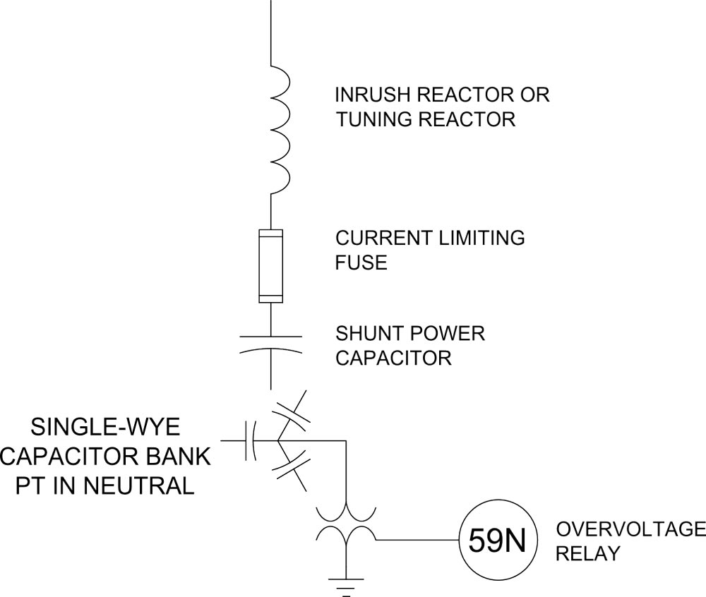
Figure 1 – Topology of the Split-Wye Neutral Current Detection Scheme
2.3 How the Scheme Operates Under Balanced and Unbalanced Conditions
Balanced Conditions
When the capacitor bank is healthy, the two wye sections are electrically balanced, and their neutral points remain at substantially the same potential. Under these conditions, little or no current flows through the CT installed between the two neutrals.
A key benefit of the split-wye neutral current scheme is that external system voltage unbalance generally affects both wye sections in a similar manner. Because the relay measures the differential current between the two halves of the bank, the scheme is not sensitive to remote line-to-ground faults or general system voltage unbalance in the way that methods based on neutral voltage displacement are.
Unbalanced Conditions
When a capacitor element fails, a fuse operates, or another internal condition changes the capacitance of one wye section, the balance between the two halves of the bank is disturbed. This causes a current to flow between the two neutral points, and that current is measured by the neutral CT. The protection relay uses this signal to detect internal bank unbalance and to initiate an alarm or trip as required. The objective is to identify the condition before the resulting voltage rise on the remaining healthy capacitor units leads to further fuse operations, capacitor damage, or loss of intended bank or filter performance.
2.4 Advantages and Limitations of the Split-Wye Neutral Current Detection Scheme
Split-wye neutral current detection is one of the most widely used indirect unbalance protection methods applied on medium-voltage power capacitor banks and harmonic filter banks. IEEE C37.99 recognizes this unbalance current detection method as an established protection method for grounded and ungrounded double-wye banks, and notes that the double-wye arrangement can provide greater flexibility, security, and faster protection because system zero-sequence unbalance tends to affect both wye sections similarly, while an internal capacitor failure appears as a neutral unbalance signal.
A key advantage of the split-wye neutral current scheme is that it is not sensitive to normal system voltage unbalance and remote ground faults like neutral-voltage-based schemes. Because it compares the two wye sections differentially, it only responds to internal bank unbalance rather than to external system conditions that affect both sections similarly. It also avoids the use of a neutral potential transformer (PT) and therefore avoids the TRV- and restrike-related switching concerns associated with neutral voltage schemes. For these reasons, VarStec prefers split-wye neutral current detection over neutral voltage detection whenever an indirect unbalance protection system is needed.
The split-wye scheme does have important limitations. First, it requires a double-wye bank configuration, which can increase capacitor count, enclosure size, and cost when compared with a simpler single-wye neutral voltage scheme. This is more of an issue on capacitor banks that could be built with just three capacitors instead of six capacitors per stage. Second, it is still an indirect method. It does not directly monitor the physical status of the fuse. Instead, it detects the electrical unbalance caused by fuse operation, failed elements, or loss of capacitance. Third, IEEE C37.99 notes that canceling failure conditions can occur in wye-wye banks, where failures in opposite wye sections offset one another and produce little or no neutral current signal even though the bank remains unbalanced.
Other blown fuse detection approaches, including neutral voltage unbalance detection and direct blown fuse detection, are also widely used in medium-voltage capacitor bank applications and are addressed separately in other VarStec Engineering Briefs. For metal-enclosed capacitor banks and harmonic filter banks, VarStec’s view is that split-wye neutral current detection is the preferred indirect method, when used, but direct fuse sensing should always be used because it directly monitors fuse operation and can also detect or prevent fuse failure associated with thermal overload operation in the prohibited zone, which indirect neutral current and neutral voltage schemes do not directly detect.
3. Engineering Considerations and Setting the Relay
To properly apply split-wye neutral current detection, relay settings should be based on the actual capacitor bank topology and on calculated unbalance quantities for the loss of one or more fuses. IEEE C37.99 provides the accepted methodology for this work and should be used as the governing reference for alarm, trip, and coordination calculations.
3.1 Setting Philosophy
Alarm stage. The alarm setting should be sensitive enough to identify the first practical loss of capacitance while remaining secure against standing unbalance, instrument error, and normal operating variation. In many capacitor bank applications, the alarm stage is coordinated to respond to the first blown fuse or first lost capacitor unit, with margin applied to avoid nuisance operation. In harmonic filter banks, however, this alarm-first / trip-later philosophy is generally not used. Because the loss of a single capacitor unit can shift the filter tuning point and adversely affect harmonic performance, the neutral unbalance scheme is typically set to trip the affected filter bank or filter stage at the first fuse operation rather than issue an alarm and allow continued operation in a detuned condition.
Trip stage. The trip setting should be coordinated so that the bank trips and locks out before the voltage on the remaining healthy capacitor units in the affected series group exceeds 110% of rated voltage, or the specific contingency limit recommended by the capacitor manufacturer. This requires calculating the overvoltage that results from successive fuse-loss conditions and placing the trip setting accordingly.
Time delay. A short intentional time delay should be applied to the trip function so that damaging internal conditions are cleared promptly while still providing security during switching events and transient system disturbances. The final delay should be coordinated with the relay, lockout, and switching device operating times.
3.2 IEEE C37.99 Calculation Method for an Ungrounded Double-Wye Bank
For an ungrounded double-wye bank, IEEE C37.99 Table 3 gives a step-by-step per-unit method for calculating the capacitance change, neutral shift, overstress on the affected capacitor units, and the neutral current between the two wye sections. Using the IEEE notation, n is the number of blown external fuses in one affected parallel group, Pa is the number of parallel units in the affected wye, Pt is the total number of parallel units in the bank phase, S is the number of series groups per phase, and G = 1 for an ungrounded bank and 0 for a grounded bank.
| Quantity | Equation |
| Parallel group per-unit capacitance | Cg = (Pa – n) / Pa |
| Affected wye capacitance | Cs = (S × Cg) / (Cg × (S – 1) + 1) |
| Affected phase capacitance | Cp = (Cs × Pa + Pt – Pa) / Pt |
| Neutral-to-ground voltage shift | Vng = G × (3 / (2 + Cp) – 1) |
| Affected phase voltage | Vln = 1 + Vng |
| Voltage on the affected series group | Vcu = Vln × Cs / Cg and if Cg = 0, then Vcu = Vln × S |
| Neutral current between the two wyes | In = 3 × Vng × G × (Pt – Pa) / Pt |
These equations are the core of the setting study. In practice, the most important outputs are Vcu, because it determines when the remaining healthy capacitor units become overstressed, and In, because it is the actual neutral current quantity used to set the relay pickup for the split-wye current scheme. All of these values are expressed in per-unit, with normal healthy-bank conditions taken as 1.0 per-unit.
3.3 Practical Application Notes
In practice, the procedure is straightforward: calculate the one-fuse condition, then calculate the two-fuse, three-fuse, and higher-loss conditions as needed. Determine the step at which Vcu exceeds the allowable capacitor-unit voltage limit, and then place the trip setting between that step and the previous step. Set the alarm low enough to detect the earliest practical loss of capacitance, but high enough to avoid nuisance operation from standing unbalance and instrument error.
For harmonic filter banks, additional care is required. For harmonic filter banks, the normal practice is to trip the affected filter bank or filter stage for a single fuse operation because operation in a detuned condition may create unacceptable harmonic performance or resonance risk. If there is a desire to continue operating after the first fuse operation, a harmonic analysis should be performed to determine whether the system can operate acceptably in that condition. VarStec’s filter design tools can be used to evaluate the resulting filter tuning point for single or multiple fuse operations, but a separate harmonic analysis is required to assess system impact. Contact VarStec for application guidance when continued operation following a fuse loss is being considered.
Inherent bank unbalance must also be considered. Manufacturing tolerance, system unbalance, sensing-device error, and temperature variation can all affect the standing unbalance seen by the relay. Compensation may be beneficial when the unbalance error approaches the alarm setting. Relays that provide compensation for inherent bank unbalance can facilitate more sensitive and reliable protection for split-wye neutral current schemes.
Finally, the calculated settings should be verified during testing and initial energization. The unbalance relay installation should be calibrated to confirm proper pickup and time delay, and the measured signal should be checked against the calculated values. Excessive trip delay can result in severe damage to the capacitor bank and associated equipment.
4. Standards and Additional Resources
- IEEE Std C37.99 (Guide for Protection of Shunt Capacitor Banks): Provides the foundational theory, mathematical formulas, and step-by-step setting examples for unbalance relaying in double-wye configurations.
- IEEE Std 1036 (Guide for the Application of Shunt Power Capacitors): Provides broader application guidance for shunt capacitors, including grounding, rating, and overvoltage considerations.
- VarStec Engineering Brief – Direct Blown Fuse Detection: Explains direct fuse-status detection and why it complements indirect neutral current and neutral voltage schemes
- VarStec Technical Resources: VarStec provides an online spreadsheet tool designed to instantly calculate neutral current, neutral voltage, and unit overvoltages for blown fuse conditions in accordance with IEEE C37.99 – 2012.
- Kojovic et al., “Application of Three-Phase Vacuum Reclosers for Capacitor Bank Switching.” Relevant to capacitor bank switching-duty considerations, including how neutral voltage transformer applications can increase TRV severity during switching.
5. VarStec Perspective
VarStec’s position is clear: when an indirect unbalance protection scheme is used on a medium-voltage capacitor bank or harmonic filter bank, the preferred method should be split-wye neutral current detection, not neutral voltage detection. In VarStec’s experience, neutral voltage schemes have repeatedly introduced switching-related problems in the field, particularly when applied with a neutral PT. Those issues can include PT saturation during switching discharge events, elevated transient recovery voltage (TRV) on the switching device, and an increased risk of restrike. For that reason, VarStec does not view neutral voltage detection as the preferred indirect method where a split-wye neutral current scheme can be applied.
At the same time, VarStec’s recommendation does not stop at selecting the better indirect method. VarStec also recommends direct fuse sensing wherever practical, because it does more than infer a fuse event from electrical unbalance. It directly monitors fuse operation and can also protect against fuse failure associated with thermal overload operation in the prohibited zone, which indirect neutral current and neutral voltage schemes do not directly detect. In other words, if an indirect scheme is required, VarStec’s position is to use split-wye neutral current detection; and where practical, that scheme should be supplemented with direct fuse sensing.
VarStec applies IEEE C37.99 calculation methods to determine alarm and trip settings, and those settings are established from the actual bank design rather than from generic assumptions. During routine factory testing, VarStec verifies the intended operation of the protection scheme so that the bank responds as designed to blown fuse conditions and related loss-of-capacitance events.
6. Key Takeaway
If an indirect unbalance protection scheme is to be used on a medium-voltage capacitor bank or harmonic filter bank, VarStec’s recommendation is to use split-wye neutral current detection. It is the preferred indirect method because it provides dependable sensitivity to internal bank unbalance, is not sensitive to remote line-to-ground faults and general system voltage unbalance in the way neutral voltage schemes are, and avoids the switching-duty and TRV concerns associated with a neutral PT.
That said, split-wye neutral current detection is still an indirect method. It detects the electrical result of fuse operation rather than directly confirming fuse status. For that reason, VarStec also recommends direct fuse sensing wherever practical, because it directly indicates fuse operation and also protects against fuse failure modes that indirect neutral current and neutral voltage schemes do not detect.
7. Contact / Further Information
For engineering guidance, application review, or equipment support related to metal-enclosed capacitor banks, harmonic filter banks, blown fuse detection, switching duty, or motor-start solutions, contact VarStec. VarStec combines practical engineering expertise with equipment solutions for medium-voltage reactive compensation and power quality applications.
About the Author
Paul B. Steciuk is Co-Founder and President of VarStec Power Solutions and a subject matter expert in medium-voltage reactive compensation and power quality, specializing in the design, development, and manufacturing of fully integrated metal-enclosed capacitor banks and harmonic filter banks. His technical expertise spans the entire project scope, from initial harmonic and power system analysis through to the physical design, manufacturing, and final commissioning of specialized reactive compensation power equipment.
Before co-founding VarStec, Paul co-founded and led Northeast Power Systems, Inc. (NEPSI) for more than 25 years, supporting consultants, EPCs, utilities, and industrial users worldwide. He earned his degree in electric power engineering from Rensselaer Polytechnic Institute (RPI), began his career at Power Technologies, Inc. and Commonwealth Sprague Capacitor, Inc., and has authored more than 30 technical articles and white papers on reactive compensation, harmonic analysis, and harmonic filter applications.