
A practical guide to the difference between steps and stages in medium-voltage capacitor banks and harmonic filter banks, including how modern controller flexibility, voltage rise, load profile, tariff structure, and switching economics influence stage selection.
Brief No.: VEB-004
Category: Control / Power Factor Correction / Capacitor Banks / Harmonic Filter Banks
1. Introduction
The terms steps and stages are often used interchangeably, but they are not the same. That distinction matters because it affects control resolution, equipment cost, enclosure size, switching duty, and overall performance.
A proper design requires more than selecting total kvar. It also requires selecting the number of stages, the number of available steps, and the stage size. While modern controllers are more flexible than earlier designs, good engineering still requires review of voltage rise, operating profile, project economics, switching duties, and filter performance during out-of-sequence stage operation. The distinction also matters when evaluating vendor bids, since two proposals may offer the same number of steps while differing significantly in stage count, cost, complexity, and performance.
2. Technical Discussion
2.1 Steps Versus Stages
A stage is a physically switched capacitor or filter group controlled by its own switching device.
A step is a switching increment available to the controller based on how those stages are sized and combined.
This distinction matters because stage count is a primary driver of cost and footprint. More stages require more switching devices, capacitors, control outputs, buswork, protection components, and, in harmonic filter banks, more iron-core reactors.
More stages also reduce switching duty, while fewer stages increase it. Step count, however, can often be increased through effective stage weighting without adding physical stages, allowing finer control at lower cost. The design objective is to select the minimum practical number of stages while still achieving the required control resolution, staying within switching device ratings, and keeping voltage change and other system impacts within acceptable limits.
2.2 Older Design Philosophy Versus Current Practice
Older automatic power factor controllers favored fixed stage ratios that increase in a binary fashion such as 1:1:1:1, 1:2:2:2, or 1:2:4:8 because their logic was built around predefined switching sequences. The NC12 documentation reflects this sequence-based design approach.
Modern controllers are more flexible. The Lovato DCRL8 allows each relay output to be assigned a weight from 1 to 32 times the smallest step, and in automatic mode it selects the optimum stage combination based on factors such as step size, number of operations, total time of use, and reconnection time. Hitachi’s RVC and RVT controllers likewise support both recognized switching sequences and other customer-programmable sequences, showing that current controller platforms extend well beyond older fixed-ratio practice.
As a result, modern capacitor banks are no longer limited to rigid legacy ratios. Even so, binary or near-binary stage sizing remains the preferred approach because it provides strong control resolution with a practical number of stages and predictable bank operation.
2.3 Stage Count Versus Step Count
The table shows that higher step count does not always require more physical stages. It also shows why step count and stage count should not be treated as the same specification item when comparing designs or evaluating vendor bids.
Table 1 – Example 3,000 kvar Bank Configurations
| Total Bank kvar |
Physical Stages |
Available Steps |
Smallest Step (kvar) |
Sequence | Stage 1 | Stage 2 | Stage 3 | Stage 4 |
| 3000 | 1 | 1 | 3000 | 1 | 3000 | — | — | — |
| 3000 | 2 | 2 | 1500 | 1:1 | 1500 | 1500 | — | — |
| 3000 | 2 | 3 | 1000 | 1:2 | 1000 | 2000 | — | — |
| 3000 | 3 | 4 | 750 | 1:1:2 | 750 | 750 | 1500 | — |
| 3000 | 3 | 6 | 500 | 1:2:3 | 500 | 1000 | 1500 | — |
| 3000 | 4 | 15 | 200 | 1:2:4:8 | 200 | 400 | 800 | 1600 |
Detailed Description of Operation
To illustrate how a 3,000 kvar, 3-stage, 6-step capacitor bank operates with a 1:2:3 stage sequence, refer to Table 2. An X in a stage column indicates that the stage is energized; a blank cell indicates that it is de-energized. As the bank moves from one kvar output level to the next, one or more stages may need to switch on, switch off, or remain energized.
Starting at 0 kvar and increasing to 3,000 kvar, the switching sequence is as follows:
- 500 kvar: Stage 1 energizes
- 1,000 kvar: Stage 1 de-energizes and Stage 2 energizes
- 1,500 kvar: Stage 2 de-energizes and Stage 3 energizes
- 2,000 kvar: Stage 1 energizes while Stage 3 remains energized
- 2,500 kvar: Stage 1 de-energizes and Stage 2 energizes while Stage 3 remains energized
- 3,000 kvar: Stage 1 energizes while Stages 2 and 3 remain energized
This example helps illustrate an important point: moving from one step to the next does not always mean simply adding another stage. In many cases, one stage must switch off while another switches on to reach the next required kvar level. As the number of steps increases, the number of switching operations can also increase significantly. Since switching devices have finite operating life, often expressed as a maximum number of operations, step resolution should be selected carefully and only as fine as necessary to meet the project requirements.
Table 2 – Sample Switching Sequence for a 3 Stage, 6 Step Capacitor Bank
| Bank kvar Requirement |
Stage 1 500 KVAR |
Stage 2 1000 kVAR |
Stage 3 1500 kvar |
| 0 | |||
| 500 | X | ||
| 1000 | X | ||
| 1500 | X | ||
| 2000 | X | X | |
| 2500 | X | X | |
| 3000 | X | X | X |
3. Engineering Considerations
3.1 Stage Size
Stage size and stage arrangement should not be selected from controller capability alone. They should be selected based on the electrical system, the operating load profile, the power factor penalty structure, and the rating and economics of the switching method.
Voltage Rise and Voltage Dip
One important design constraint is voltage rise and voltage dip. When a capacitor stage is energized, reactive power is injected into the system, producing a voltage rise at the point of connection. When a stage is de-energized, that reactive support is removed, producing a voltage dip. As a practical design guideline, the voltage change associated with switching a single capacitor stage should not exceed 3%.
The per-unit voltage change is given by:
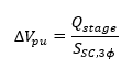
Where:
- = stage size in MVAR
- = three-phase short-circuit MVA at the capacitor bank bus
To convert to percent:
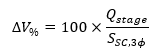
This shows that larger stages produce larger voltage changes, and weaker systems with lower short-circuit strength experience greater voltage change for the same stage size. Therefore, the largest stage should be limited so that its switching does not produce more than a 3% voltage change.
Switching Device Rating
In addition to voltage change, stage size must also be checked against the switching device rating. The device must be suitable for capacitor switching duty, whether it is a contactor, capacitor-duty vacuum switch, or circuit breaker, and it should be tested to the applicable standards for that service.
The switching device should be rated for at least 1.35 times the stage current and must also withstand the peak transient inrush current during energization. As stage size increases, switching duty also increases, which may require larger inrush-current-limiting reactors. Reactor cost and space therefore become additional design considerations.
Available switching devices are often the leading factor in selecting stage size and switching sequence. Their cost, reliability, lead time, performance, and field-proven service record directly shape the final design.
For further information on switching duty, see VarStec’s Transient Inrush Calculation Tool, which quantifies the expected transient inrush current and frequency for the proposed stage arrangement. It is a practical design aid for checking switching-device capability and evaluating the need for current-limiting reactors.
3.2 Operating Load Profile and Power Factor Penalty Structure
Tariff Structure
If the capacitor bank is being installed to satisfy a utility tariff and justify the investment through payback, the tariff structure becomes a major factor in selecting the number of steps and stages. The objective is not only to meet the tariff requirement, but to do so with the minimum practical number of stages while still satisfying the other engineering constraints.
Tariff structures vary widely. Power factor penalties may be based on kVA demand, average monthly power factor, power factor at the time of monthly peak demand, or other utility-specific billing provisions. Some tariffs also include ratchet provisions, where a penalty condition can affect billing for an extended period.
For that reason, the tariff structure is often a leading factor in capacitor bank sizing, stage size, and step selection. Understanding the rate structure is essential to choosing the proper bank arrangement.
Operating Load Profile
The operating load profile must also be considered when selecting the number of steps and stages. A system with widely varying reactive demand typically requires more control resolution than a system with a stable load. If the stages are too large, the bank may alternate between under-correction and over-correction rather than track the load effectively.
When a capacitor bank is being applied to satisfy a tariff or penalty structure, the operating load profile and the tariff must be considered together. The selected stage sizes must support both the billing objective and the actual reactive demand of the facility. The goal is to provide sufficient control resolution without adding unnecessary stages, switching devices, cost, or complexity.
3.3 Switching Economics
The number of stages must also be reviewed from a switching-equipment standpoint. The switching device may be a vacuum breaker, vacuum contactor, or vacuum switch. Cost, footprint, switching duty, reliability, maintenance, and lead time all influence the preferred number of stages.
More stages improve control resolution, but they also increase device count, enclosure size, wiring, control complexity, and cost. Fewer stages reduce cost and simplify construction, but they may reduce control resolution or produce excessive voltage change per switching event.
The best design is usually not the one with the most stages. It is the one with the fewest stages that still meets the required performance objective and remains practical with available switching technology.
3.4 Harmonic Filter Perspective
When evaluating stage sequence, it is important to distinguish between a capacitor bank and a harmonic filter bank. In a harmonic filter bank with multiple tuning points, the stages must operate in a specific order. In nearly all cases, lower-order tuned filters must be energized before higher-order tuned filters.
For example, in a typical 5th, 7th, 11th harmonic filter bank used on a rectifier or VFD system, the 5th stage must be energized before the 7th, and the 7th must be energized before the 11th. This is usually a strict requirement, which means out-of-sequence operation is not permitted and the operating sequence is effectively predefined.
By contrast, if a filter bank consists of multiple stages all tuned to the same frequency, such as three stages all tuned to the 5th harmonic, out-of-sequence operation may be possible. Harmonic filter banks therefore often impose additional restrictions on stage sequence, and those restrictions must be considered when selecting stage sizes, stage sequence, and controller programming.
3.5 Medium-Voltage Perspective
Stage sizing philosophy in medium-voltage systems is not the same as in low-voltage automatic banks. At medium voltage, switching devices are typically available only in relatively large current ratings, bus ampacities are generally manageable, and system short-circuit strength is often much higher than in low-voltage applications. These conditions often support the use of larger stages than many engineers initially expect.
That said, larger stages should not be selected by default. They should be selected only after checking voltage change, system performance, tariff compliance, switching duty, and switching economics.
4. Standards and Additional Resources
- IEEE 1036-2020, IEEE Guide for the Application of Shunt Power Capacitors — Primary IEEE application guide for shunt power capacitors rated 2400 Vac and above. It is the most directly relevant reference for capacitor application, ratings, control considerations, switching, harmonics, protection, and bank application.
- IEEE Std 141-1993, IEEE Recommended Practice for Electric Power Distribution for Industrial Plants (IEEE Red Book) — Broader industrial power distribution reference. For this topic, its value is centered in Chapter 8, which addresses power-factor improvement, reactive power location, switched-capacitor controls, switching transients, capacitor-bank protection, resonance and harmonics, and inspection and field testing.
- Lovato Electric, DCRL Series Controller Literature — Useful as a modern controller reference because it shows that current controller platforms do not depend on rigid legacy step sequences. Lovato states that, in automatic mode, the controller calculates the optimum capacitor-step configuration using factors such as step size, number of operations, total time of use, and reconnection time. https://catalogue.lovatoelectric.com/gl_en/Automatic-power-factor-controller-DCRL-series-8-steps/DCRL8/snp
- Gentec, N12 and NC12 Series Controller Literature — Useful as a legacy reference because it reflects traditional step-sequence philosophy and documents classic stepping programs such as stack, normal, circular, and optimal. It helps explain the historical basis for sequence-based stage design. https://gentec.ca/fra/produits/serie-n12-et-nc12.asp
- Hitachi Energy, RVT Power Factor Controller Literature — Useful as a comparative reference because it documents both recognized step sequences and customer-programmable sequences, showing how modern controllers allow flexibility beyond older fixed-ratio approaches. https://www.hitachienergy.com/products-and-solutions/capacitors-and-filters/low-voltage-capacitors-and-filters/power-factor-controllers/rvt
5. VarStec Perspective
VarStec’s position is that engineers should not specify only the number of steps when applying a medium-voltage capacitor bank or harmonic filter bank. The design should address total kvar, number of stages, preferred stage weighting, acceptable single-stage voltage rise, operating load profile, tariff objective, and switching technology.
VarStec also recognizes that older design philosophies have changed. It is no longer necessary to force every design into rigid step ratios solely because of controller limitations. Modern controllers allow more flexible stage weighting and more intelligent automatic selection of capacitor combinations.
Even so, VarStec generally prefers binary or near-binary sizing where practical, because it provides strong control resolution, keeps the switching sequence logical, and usually produces the best balance between performance and equipment count.
Most importantly, VarStec does not treat stage sizing as a controller-setting exercise alone. Proper stage selection requires review of voltage rise, operating profile, penalty structure, and switching-device economics. As a manufacturer of metal-enclosed capacitor banks, harmonic filter banks, and motor-start solutions, VarStec provides both the engineering support and the equipment needed to implement the selected design.
6. Key Takeaway
Stages are the physically switched kvar groups.
Steps are the available control increments created by those stages.
Modern controller capability has relaxed many of the strict sequence limitations that influenced older design practice. Even so, binary or near-binary stage sizing still remains the preferred starting point for most applications.
Final stage size should be selected only after checking four things:
- Single-stage voltage rise
- Operating load profile
- Power factor penalty structure
- Switching-device economics
7. Contact / Further Information
For engineering guidance, application review, or equipment support related to metal-enclosed capacitor banks, harmonic filter banks, power factor correction, switching duty, or motor-start solutions, contact VarStec. VarStec combines practical engineering expertise with equipment solutions for medium-voltage reactive compensation and power quality applications.
About the Author
Paul B. Steciuk is Co-Founder and President of VarStec Power Solutions and a subject matter expert in medium-voltage reactive compensation and power quality, specializing in the design, development, and manufacturing of fully integrated metal-enclosed capacitor banks and harmonic filter banks. His technical expertise spans the entire project scope, from initial harmonic and power system analysis through to the physical design, manufacturing, and final commissioning of specialized reactive compensation power equipment.
Before co-founding VarStec, Paul co-founded and led Northeast Power Systems, Inc. (NEPSI) for more than 25 years, supporting consultants, EPCs, utilities, and industrial users worldwide. He earned his degree in electric power engineering from Rensselaer Polytechnic Institute (RPI), began his career at Power Technologies, Inc. and Commonwealth Sprague Capacitor, Inc., and has authored more than 30 technical articles and white papers on reactive compensation, harmonic analysis, and harmonic filter applications.